HUMA Assembly Guide
HUMA is an Arduino-compatible board based on Freeduino. It is designed so you can solder every part yourself, like a classic radio kit. Basic soldering experience is enough to finish the board.
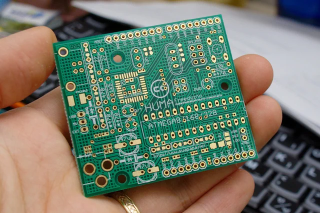
If soldering feels rusty, start with this Korean comic guide to soldering.
HUMA is open-source hardware. We take no responsibility for damage to the board or any personal or material harm that may occur while assembling or using it.
Schematics, artwork, and related documents are licensed under CC BY-SA.
Tools and parts
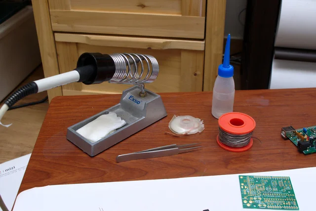
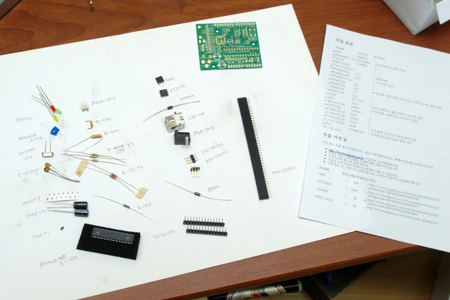
Prepare the HUMA PCB and every item on the parts list.
Soldering
Solder from lowest parts to tallest, from the center of the board outward, and from heat-tolerant parts to heat-sensitive ones.
Start with the lowest 3.3V SMD capacitor. The plus (+) side is marked with a stripe.
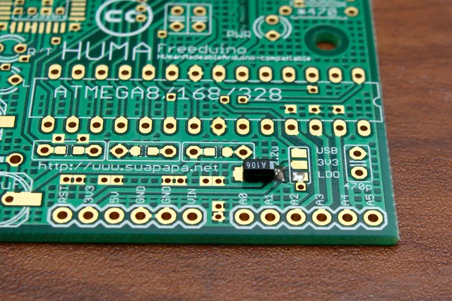
Align the stripe toward the 2.2u marking, tack one pad first, then finish the other.
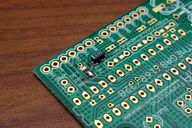
Then bridge the solder jumper next to the capacitor to connect USB and 3V3. That routes the FT232BL USB-serial chip's 3.3V onto the board rail.
Next solder the USB-serial chip FT232BL (or FT232BM). If you are new to SMD ICs, see this SMD soldering guide (Korean).
Seven 100nF capacitors are used. Pads accept either SMD 1608 or disc ceramic parts. If you chose SMD, solder them now. 100nF caps are non-polar.
The hardest SMD work on this board is done.
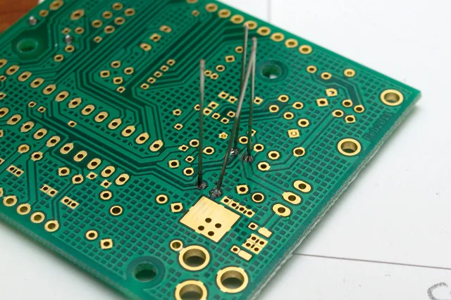
Install resistors to the values marked on the board. Use ordinary 1/4W or 1/8W 5% resistors. 1% parts cost more without benefit in this digital circuit. 1/2W parts are bulkier and harder to fit.
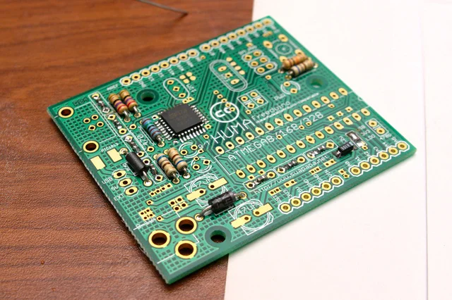
Solder the diode by the power jack and the ferrite bead under the USB connector. Instead of the bead you may fit a resettable fuse in the PTC0805 footprint, as on official Arduino boards. Choose one of the two.
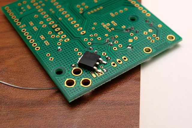
Flip the board and solder the 7805. Tack one lead first to hold position,
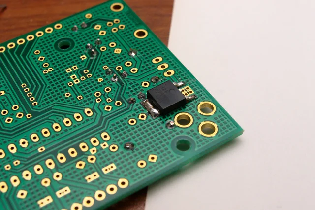
then solder the remaining pads once it sits flat.
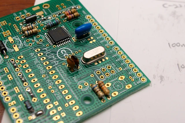
Solder the resonator (blue) and the crystal (silver).
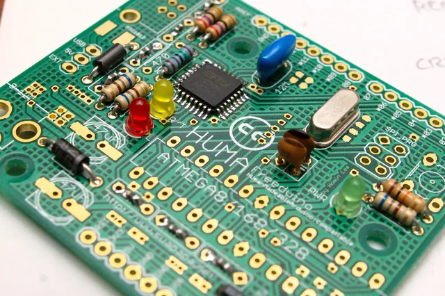
Fit three 3mm LEDs. Observe polarity: the short lead (or flat edge) faces the silk labels (R/T, L, PWR).
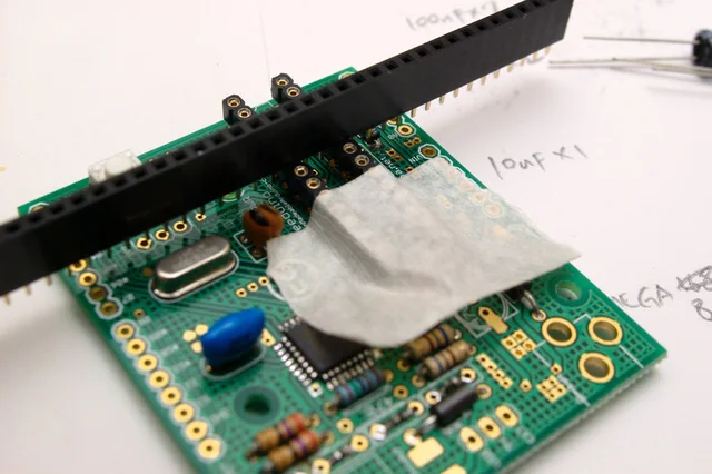
Install the ATmega IC socket. The photos use a cut-to-length socket, taped and braced with pin-header sockets before soldering.
If you skipped the SMD 100nF caps earlier, solder seven ceramic 100nF caps now.
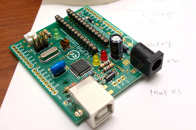
Fit 47uF-100uF electrolytics (or solid caps). SMD footprints are also provided. Orient the white stripe (-) toward the flat side of the silk outline.
Then solder the USB connector, power jack, reset switch, and ISP pin header.
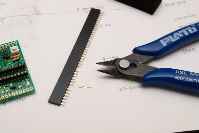
You need two 6-pin and two 8-pin female headers for shields. If you bought long strips, pull the pin at the cut point with pliers,
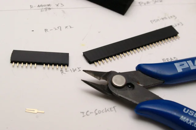
then cut the plastic at that gap.
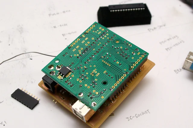
An Arduino shield plugged into the sockets keeps them square while soldering. Without one, tape them vertical. Tack the end pins first, remove the shield, then finish the rest.
Soldering is done. Insert the ATmega into the socket, matching the notch.
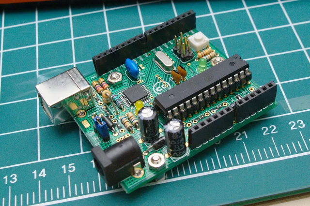
Fit the power-select jumper (USB / external) to finish.
Burn the bootloader
If your ATmega did not come with an Arduino bootloader, burn one once with an AVR ISP programmer.
Prebuilt bootloader hex files ship with the Arduino IDE here:
- ATMEGA8:
hardware/arduino/bootloaders/atmega8 - ATMEGA168, ATMEGA328:
hardware/arduino/bootloaders/atmega
See also: